Options:
- Assembled board without potentiometer
- Assembled board + ALPS-27 type 4-gang potentiometer
- Complete set (as shown in pictures, excluding power supply connections)
Inspired by the Marantz flagship SC-7S2 preamplifier, capturing its essence.
This project meticulously recreates various core amplification architectures from the original design, a substantial undertaking.
Component/part numbering largely aligns with the original schematic for traceability.
Interested enthusiasts are encouraged to patiently review this page to understand the various operating modes.

Original partial stage circuit diagrams are provided; full original schematics are available for purchasers.
For this personal design, aiming for superior sound quality:
The core HDAM-SA3 modules are used, directly upgraded from the HDAM-SA modules used in the original 7S2.
The onboard SA buffer circuits for the original fully balanced input and CD input channels also directly utilize SA3 modules.

Main Board Specifications:
Dimensions: 170mm x 185mm x 30mm (H)
Main Power Supply: DC ±22V
Auxiliary Power Supply: AC Dual 9V, or AC Single 9V

Functional Modes:
1. Fully Balanced XLR Input → Fully Balanced Amplified Output
Suitable for balanced sources + balanced power amplifiers.
2. Single-Ended RCA Input → Converted to Fully Balanced XLR Output
Suitable for single-ended sources + balanced power amplifiers.
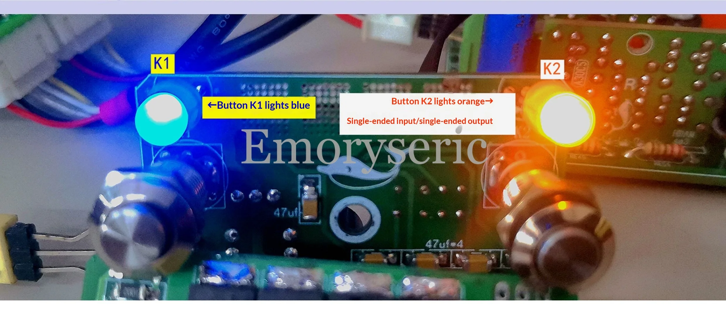
3. Single-Ended RCA Input → Single-Ended Amplified Output
Suitable for single-ended sources + single-ended power amplifiers.

Both the main board and HDAM modules feature a mirror-symmetry design.
A total of 24 HDAM-SA3 modules are installed.

HDAM-SA3 Module:
Current Feedback / High-Speed Discrete / Ultra-Dynamic Amplification Circuit.
Also known as a Push-Pull Complementary Cascode Amplifier circuit.
Represents a performance leap of two generations compared to the HDAM-SA, offering significantly superior performance.

In all three modes, audio signal consistency across channels is excellent.
Sound Characteristics: Clear, transparent, rich in detail.
Excellent noise suppression, far exceeding pure single-ended methods.
Faithfully captures the essence of the original SC-7S2 style.
Listeners can directly experience the distinctive timbre of the Marantz SC-7S2.
Mode switching via the control board is detailed in the following images.


Main Board → Component Overview:
Resistors: Beijing 718, Taiwan HOLYMA/HS, BI trimmer pots.
Capacitors:
Elna RFS Silmic (Brown) x12, Elna Axial x4,
Nichicon MUSE x6, PH Axial x4, BC x16, Panasonic Non-Polarized x12.
Diodes:
ROHM SLR-332MG3F x12,
Hitachi 1SS133 (or Toshiba 1SS176) x144.
Transistors:
Main Board: A970/C2240 (or A988/C1841) - 24 pairs.
Sub-board/Module: A1266/C3198 (or A1268/C3200) - 96 pairs.
Relays: EC2-5 x8.

Regarding Power Supply:
Can use one power supply for both channels.
Recommended: Independent power supplies for each channel (mono blocks).
The power supply board shown below is based on the original regulator circuit.
It retains the advantages of the original power supply architecture but incorporates technical improvements:
Output voltage changed from fixed regulation to 3-terminal adjustable regulation.
Enables automatic fine-tuning of output voltage, ensuring consistency.
Features a "one-drags-two" Darlington regulator transistor configuration.
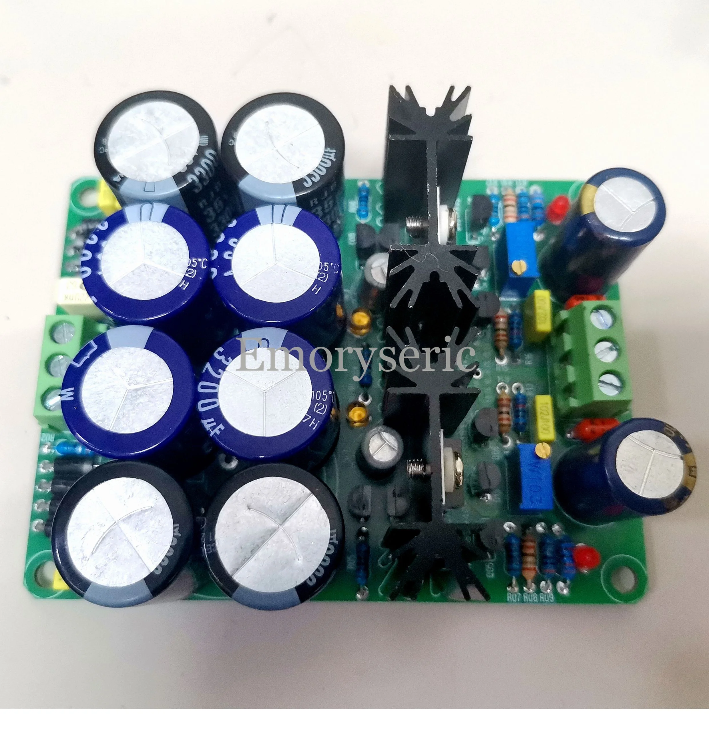

After extensive listening tests and tuning, the main filter utilizes a hybrid array of 4 Elna + 4 Nippon Chemi-Con capacitors.
Total capacitance reaches 26,000μF, with noticeable effect.
Accommodates up to 2 capacitors max. Ø35mm, and 8 capacitors max. Ø18mm.


